
Guide: Select the Proper Pin Configuration for Your M5 Circular Connector Project
As industrial automation moves toward miniaturization and high-density integration, M5 circular connectors have become the preferred connection solution for miniature sensors, compact detection equipment and embedded systems with their ultra-small size and reliable connection performance. As a core parameter of connector selection, pin configuration directly determines the functional adaptability, signal transmission quality and system expansion space of equipment. This article systematically sorts out the pin configuration types, function definitions and selection logic of M5 circular connectors to help engineers make accurate matches in projects.
1. Mainstream Pin Configuration Specifications of M5 Circular Connectors
Limited by the physical size of 5mm thread outer diameter, M5 connectors have a relatively streamlined number of pins. The mainstream industry specifications are concentrated in 3-pin and 4-pin types, both of which comply with the IEC 61076-2 series of industrial connector standards, ensuring basic interchangeability of products from different manufacturers.
1.1 3-Pin Configuration: Standard Choice for Basic Sensing Connections
The 3-pin configuration is the most widely used basic type of M5 connectors, designed for power supply and single-channel signal transmission of simple sensors. Within the limited space, the 3-pin layout balances contact spacing and insulation performance, making it the standard interface for 2-wire and 3-wire sensors.
Typical pin function allocation follows general industrial specifications:
- Pin 1: Positive power supply (V+), commonly compatible with 24V DC industrial power supply
- Pin 2: Signal output terminal, carrying switch or analog signals
- Pin 3: Negative power supply / Ground terminal (GND/V-)
This configuration features a simple structure, controllable cost, and high fault tolerance for plugging and wiring, making it suitable for terminal detection nodes with single functions.
1.2 4-Pin Configuration: Extended Solution for Multi-Function Scenarios
The 4-pin M5 connector adds an independent channel based on the 3-pin version, supporting dual-channel signal output, differential signal transmission or additional control functions. It is a balanced choice that takes both size and functional scalability into account.
Common 4-pin function definitions in the industry are divided into two categories:
- General Signal Type : Pin 1 V+, Pin 2 Signal 1, Pin 3 V-, Pin 4 Signal 2, suitable for dual-output sensors (such as PNP+NPN dual output, dual switch detection)
- Differential Signal Type : Pin 1 V+, Pin 2 Signal+, Pin 3 Signal-, Pin 4 V-, used for transmitting 4-20mA current signals or 0-10V voltage signals, improving stability in electromagnetic environments through differential transmission
The 4-pin configuration expands application boundaries without significantly increasing the volume, and is the mainstream choice for smart sensors and small detection modules.
2. Typical Application Scenario Matching for Different Pin Configurations
The selection of pin count is essentially a quantitative match for equipment functional requirements. Combined with actual usage habits in industrial scenarios, the two configurations each have clear applicable fields.
Preferred Scenarios for 3-Pin Configuration
- Basic switch sensors: proximity switches, photoelectric switches, Hall sensors and other devices that only require power supply and single-channel switch signal output
- Miniature temperature/pressure sensors: compact detection elements with simple analog output that have extremely high requirements for space occupation
- 2-wire instruments: low-power detection devices where power supply and signals share a loop, with low pin resource occupation
- Large-scale distributed nodes: simple sensor nodes deployed in large quantities on production lines, where the 3-pin configuration has significant cost advantages
Preferred Scenarios for 4-Pin Configuration
- Smart sensors: sensors with self-diagnosis and parameter configuration functions that require additional channels to transmit configuration signals
- High-precision analog detection: pressure and flow sensors using differential signal transmission with high anti-interference requirements
- Dual-output detection equipment: miniature devices that output both switch and analog signals, or have two independent detection channels
- Small industrial communication nodes: miniature devices for short-distance low-speed communication that need to carry both power supply and data transceiving
3. Core Judgment Dimensions for Pin Configuration Selection
Choosing a pin configuration is not "the more the better". Redundant pins will increase costs, occupy space and reduce insulation margin. It is recommended to comprehensively evaluate from the following four dimensions during selection.
3.1 Signal Transmission Demand: Function First Principle
First sort out the types and quantities of signals that the equipment needs to transmit: for scenarios that only require power supply + single-channel signals, 3 pins are sufficient; consider the 4-pin solution only when there are requirements for differential signals, dual-channel output or control signals. Special attention should be paid that under M5 size, it is not recommended to mix power supply and high-frequency signals to avoid electromagnetic crosstalk affecting signal quality.
3.2 Installation Space Constraint: Size First Principle
The core advantage of M5 connectors lies in miniaturization. If the internal wiring space of the equipment is extremely tight, the 3-pin configuration has smaller plugs and sockets, lower welding and assembly difficulty, and the cable outer diameter can be reduced accordingly, which is more conducive to the miniaturization design of equipment.
3.3 Environmental Anti-Interference Requirement: Reliability First Principle
In scenarios with complex electromagnetic environments (such as near frequency converters and around servo motors), the anti-interference ability of differential signal transmission is significantly better than single-ended signals. In this case, the 4-pin configuration should be prioritized to improve signal transmission stability through differential pin pairs and avoid signal misjudgment caused by interference.
3.4 System Expansion Planning: Forward-Looking Principle
If the equipment has the possibility of functional upgrade in the future, reserving pin resources can reduce iteration costs. For example, projects that currently only use single-channel signals but plan to add status feedback functions later can directly choose the 4-pin configuration to reserve channels for subsequent upgrades, avoiding re-molding and interface replacement.
4. Common Misconceptions and Precautions in Selection
4.1 Avoid Blindly Pursuing More Pins
M5 connectors have limited physical size. An increase in the number of pins will lead to a decrease in single-pin current carrying capacity and insulation spacing. For scenarios that only require basic connection, the 3-pin configuration has better electrical reliability and mechanical strength.
4.2 Pay Attention to Consistency of Wiring Sequence Standards
Pin definitions may vary among different manufacturers. During selection, it is necessary to confirm whether the pin allocation complies with the wiring specifications of the equipment end. Octopusconn M5 series connectors all follow general industrial pin definitions, which can be directly adapted to standard sensor interfaces and reduce the risk of wiring errors.
4.3 Protection Grade Is Irrelevant to Pin Configuration
The IP protection grade depends on the sealing structure design of the connector and has no direct relationship with the number of pins. Octopusconn M5 full series connectors all reach IP67 protection grade, and both 3-pin and 4-pin models can work stably in harsh industrial environments such as humidity and dust.
4.4 Synchronous Selection of Supporting Cables
The number of pins corresponds to the number of cable cores. The 3-pin configuration is usually matched with 24AWG cables, and the 4-pin configuration requires thinner wire diameter or slightly larger outer diameter cables. During selection, the bending radius, oil resistance and temperature resistance of the cable should be confirmed simultaneously to ensure the environmental adaptability of the overall solution.
5. Octopusconn M5 Connector Product Support
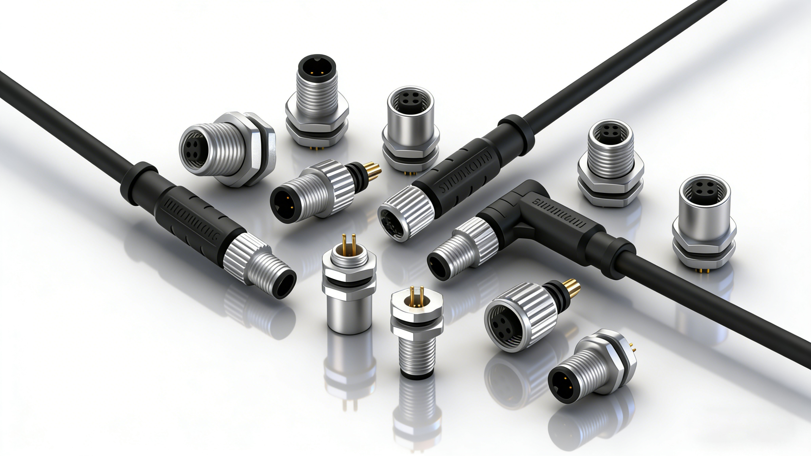
Octopusconn M5 circular connector series covers mainstream 3-pin and 4-pin configurations, providing various forms such as overmolded plugs, field assembly plugs and sockets. With brass nickel-plated shells and gold-plated contacts, it delivers industrial-grade reliable performance including IP67 water and dust resistance, vibration resistance, and high and low temperature resistance while maintaining an ultra-compact size. The full series of products are CE and FCC certified, widely compatible with miniature sensors, automatic detection modules and compact industrial equipment.
For special project requirements, Octopusconn R&D team can provide customized pin definition, cable length and material selection services, responding throughout the whole process from prototype verification to mass production, helping customers quickly implement equipment connection solutions.
 telephone
 Contact US